


DYNO / ROLLING ROAD
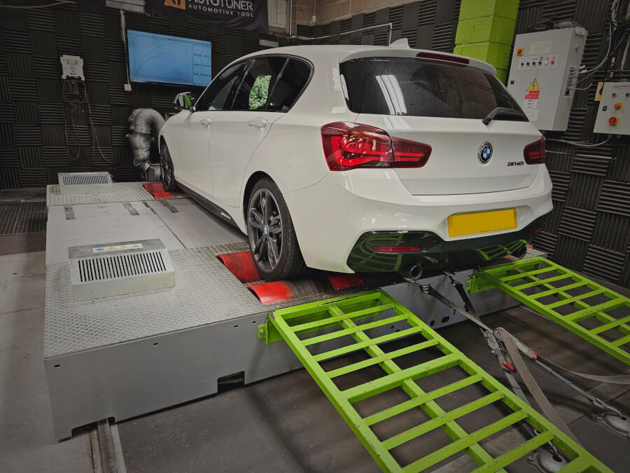
Check your car’s health on our state-of-the-art 4WD dyno
Welcome to Mobile Eco Tuning (MET), your local engine mapping specialist for the Bristol area. Based in Weston Super Mare, our workshop boasts state-of-the-art tuning facilities including our 1000bhp 4WD dyno, dedicated diagnostic tools, and specialist remapping equipment.
Specialising in engine control unit diagnostics and tuning, our team of experts are able to alter the vehicle’s software settings to increase power and torque, and improve mpg.
Contact MET today to unlock the true potential of your vehicle and take things to the next level.
Contact UsCheck your car’s health on our state-of-the-art 4WD dyno
Restore your diesel vehicle’s full performance with a DPF refurb
Unlock horsepower and torque increases with our engine tuning
Enhance your car’s transmission with a MET calibration upgrade
Specialised tuning for HGV, agricultural and construction vehicles
Check your car’s health on our state-of-the-art 4WD dyno
Restore your diesel vehicle’s full performance with a DPF refurb
With a dedicated network of authorised agents throughout the UK, you can unlock the performance potential of your vehicle with an MET remap no matter where you live! Every one of our 150-plus agents has undergone specialist training with MET products and provides the professional service associated with the MET brand. Many of our agents offer mobile tuning solutions, making remapping your car or van even easier.
Simply enter your postcode to find your nearest authorised MET agent.
My VW Sharan was experiencing huge problems with the ECU modules and became un-startable during an incredibly frustrating few days, and I felt on the verge of scrapping it. I would have been forced to...
Read more
Previously used Mobile Eco Tuning for a Stage 1 Economy remap on my 2.0 diesel, huge improvement in drivability and good gains on fuel economy, more recently took a different car in and after inspection...
Read more
They 100% know what they’re talking about. Have been having trouble with the DPF on my Audi. I live in Cornwall and had a couple people look at it in my area, but with no...
Read more
I cannot recommend the service at Ecotune more highly! Brought my civic turbo to the guys here after doing some modifications to the setup and needed a whole new map installing on the ECU as...
Read more
Previously took my Focus to MET in April 23 for a eco focused remap, excellent improvements in driveability and MPG! I now have a different car and first on my list was back for another...
Read more
I drove the 70 miles up to Weston-Super-Mare from South Devon to have my car remapped and I was very pleased that I did. It is a very clean and professional outfit and from the...
Read more
Ready to experience the full potential of your vehicle? Book a remap with MET today!
Based in Weston Super Mare with easy access from J21 of the M5, we are well placed to serve car enthusiasts in Bristol, Somerset, Gloucestershire, Wiltshire, and Wales. Take a look at what MET can do for your vehicle, and book a remap now!
Book a Remap


